Expand Stroke Facility
The Expand Stroke facility traces a closed, convex contour (referred to as the “nib”) along a “source” contour, producing a new contour or contours that enclose the area the nib “passed over”. When the source contour is open the result is usually a single closed contour, and when the source contour is closed the result is usually two closed contours:

Typical Examples
There are exceptions when the geometry of the nib and the source contour interact:

Unusual Examples
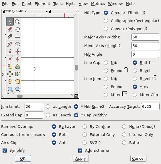
The “Expand Stroke…” dialog in the “Element” menu of a font view or outline view window is the primary interactive interface for the facility. In the font view it traces all foreground contours in all selected glyphs. In the outline view it traces all contours with at least one point selected, or every contour if no points are selected on any contour. The dialog looks like this:
The Freehand Tool also uses the facility and has a
similar dialog, and there are interfaces for both
Python and
FontForge's native scripting language.
This guide is arranged into four sections. The first discusses the common case of tracing a circular nib, which is also called “offsetting”. It includes a description of the “cap” and “join” options for offset curves.
The second section introduces the other nibs types: the rectangular “calligraphic” nibs associated with some types of calligraphy, elliptical nibs, and general convex nibs designed by the user. All nibs support the same cap and join options listed in the first section, but some have slightly different behaviors and effects.
The third section discusses additional parameters that address special cases, influence the geometric accuracy of the generated contours, or that can aid in debugging potential problems.
The last section is an overview of problems a user may encounter using the system and some potential work-arounds. Please read this section prior to filing a GitHub issue.
Offsetting
Tracing a contour with a circular nib of radius r is equivalent to “offsetting”-creating parallel contours on each side at distance r for a total line thickness of 2r (source contour shown in green):

Offset Curves
In FontForge you specify a circular nib in the UI dialog by choosing the “Circular/Elliptical” nib type and making the Major and Minor Axis lengths equal. In the native and Python API a Minor Axis value of zero will be replaced by the Major Axis value. And although it does not make a geometric difference, the recommended Nib Angle for a Circular nib is zero.
Offsetting is a longstanding way of specifying a line of fixed thickness in terms of a contour-that is, a sequence of connecting splines-combined with an offset radius. The model was common in PostScript and is currently used in the SVG graphics markup language. Most font formats do not support offset curves directly, however, so any line specified that way must be “translated” into (roughly) equivalent closed contours. This is a common use of the Expand Stroke facility.
The parallel lines determined by the contour and offset radius alone will not necessarily connect. They will all connect in the case of a source contour that is closed and has only “smooth” points:

Offsets of a smooth contour
They will not connect where the source contour is open or has “corner” points where the angle changes:

Offsets of angled and open contour
Caps
The line that closes the gap between the offset lines traced to the end of of an open source contour is called a “cap”. PostScript and SVG specify three cap styles that are really two styles: “Round” and “Butt”/”Square”. A Round cap connects the ends with a semi-circle, while a Butt cap connects them with a straight line. When tracing with a circular nib the FontForge cap options “Nib” and “Round” are both equivalent to PS/SVG “Round”, and the options “Butt” and “Bevel” are both equivalent to PS/SVG “Butt”. (These options differ when used with other nib shapes.)

Butt and Round Caps
A PS/SVG “Square” cap is a Butt cap extended by the length of the offset radius, and therefore half the width of the traced line. The FontForge “Extend Cap” parameter generalizes this feature by allowing the user to specify the distance between the end of the source contour and the cap line either as an absolute length or in units of stroke-width. The parameter works with the “Round” and “Butt” cap styles but not the “Nib” and “Bevel” styles. A PS/SVG Square cap is therefore equivalent to a Butt cap with “Extend Cap” set to 0.5 in stroke-width units.

Extend Cap Examples
Joins
When the source contour has a “corner” point with an angle change there will be one angle of less than 180 degrees and one greater than 180 degrees. The offset lines on the side with the smaller angle will intersect, and the easy solution is to trim off the parts of the line past the intersection:

Offset Trimmed At Join
The offset lines at the larger “reflex” angle do not meet. The line closing the gap between those is called a “join”. PostScript specified three join styles: “Round”, “Bevel” and “Miter”. SVG 2.0 adds styles “Miter Clip” and “Arcs”. FontForge currently supports the six styles “Nib”, “Bevel”, “Round”, “Miter”, “Miter Clip”, and “Arcs”.
A PS/SVG “Bevel” join connects the two offset curves with a straight line, and this is also what FontForge’s “Bevel” option does. A PS/SVG “Miter” or SVG “Miter Clip” join (normally) extends each offset curve with a straight line tangent to the curve at the endpoint to where each intersects, as do FontForge’s equivalent “Miter” and “Miter Clip” options. A FontForge “Nib” join connects the offset curves with an edge corresponding to the shape of the nib; when using a round nib this is equivalent to the PS/SVG “Round” join option, which connects the offset lines with an arc of the offset radius. FontForge’s “Round” join option is also equivalent when using a circular nib:

Join Examples
The difference between Miter and Miter Clip is in how “long” joins are handled. The “Join Limit” parameter specifies the maximum “length” of a miter join. This limit can be specified either in em-units or (when the nib is circular) nib-widths (e.g. the diameter of the circle). The term “join length” is a bit misleading because the limit is actually calculated based on the angle of the join, and the “length” is how long the join would be if the offset curves were straight lines. There is a more complete explanation in the stroke-miterlimit” section of the SVG specification. With the Miter style a join that exceeds the join limit “falls back” to a Bevel join, while with the Miter Clip such a join is clipped at the join limit by a line parallel to the Bevel line:

Miter and Miter Clip
Note, however, that the term “limit” is also somewhat misleading, in that a Miter join is never shortened past the Bevel line, which therefore restricts the minimum length of a given join.
Like Miter Clip, the “Arcs” join style matches the position and tangent angles at each offset curve endpoint, but the curve is extended with a circular arc of matching curvature rather than a line. (In some cases the curvature of the extensions must be adjusted to ensure they intersect, in which case the curvatures at the endpoints will not be continuous.) This style is based on the SVG 2 join of the same name and should have close to the same geometry when used with a circular nib. (Arcs joins are not yet widely supported in browsers or other SVG tools and there are some ambiguities in the specification.)
Note that Arcs joins exceeding the Join Limit are clipped in a way similar to those of the Miter Clip style.
Calligraphic and Other Convex Nibs
In addition to circular nibs the Expand Stroke facility also has parameterized support for “Calligraphic” (rectangular) and Elliptical nibs. These nibs are described by Width and Height (called the Major and Minor Axes in the case of an ellipse) and a rotation Angle:

Calligraphic and Elliptical Nibs
General convex nibs
In contrast with the parameterized nibs, the shape of a Convex nib is specified as a contour which can be edited interactively in the area at the top of the dialog, created elsewhere and then pasted into that area, or set via the Python API. As the name implies the shape enclosed by the contour must be convex. Formally, a shape is convex when the line between any two points on the edge of or inside the shape does not pass through any points not inside the shape (or, if both points are chosen from the same linear edge, only passes through points also on that edge). Less formally, a shape is convex when no edges are concave or “indented”.
While these definitions may help, it is probably more useful to focus on the specific rules used by the facility to verify that a contour is convex. These rules are slightly conservative, in that some geometrically convex contours fail to meet them. (Such cases are rare in practice, and can anyway often be “repaired” by adding some points without (visibly) changing the shape.)
Note: These rules are defined in relation to a cubic contour. Although you can
design a nib as a quadratic contour, you must switch the layer to “Cubic” before
applying Expand Stroke. (Or, in the API, you must convert the contour or layer
prior to calling the stroke method or ExpandStroke function.) In
contrast, when using a Spiro nib on a Cubic layer it is not necessary to switch
into Bezier mode. However, it can still be a good idea to do so to better
understand any reported errors.
There are actually two groups of rules. The first group restrict the relative positions of on-curve points. The points must be arranged as a convex polygon, which is a non-self-intersecting (i.e. “simple”) polygon of at least 3 points/edges, where all interior angles at the points are less than 180 degrees. These points must be in the form of a closed, clockwise contour:

Convex Polygons and Exceptions
The second group of rules restrict the relative positions of the control points:
Each spline must either be a line with no control points, or have two control points positioned outside of the convex polygon. That means they can not be either inside the polygon or on the edge of the polygon.
The angle between the on-curve line and the control point line is limited by the angle to that point’s other control point. Or, if the adjacent “edge” is a line, the angle to the next on-curve point.
The control point line segment must not intersect the spline’s other control point line.
These three rules typically define a triangle (with one excluded edge) where one control point can be positioned given the positions of the other points:

Control Point Rules for Convex Shapes
Aside from the shape, the position of a convex nib relative to the origin has an effect on the output. Parameterized nibs are always centered on the origin, which leaves the output in the “same place” as the source contour. A nib offset from the origin will cause the output to be offset by that amount:

Centered and Uncentered Convex Nib Output
Caps and Joins With Other Nibs
Earlier versions of FontForge only provided cap and join options for circular and elliptical nibs (and some of the latter were misleadingly named). For other nibs it automatically closed the cap and join edges with the nib shape-equivalent to the current “Nib” cap and join styles. Given that the Nib options produce the shape that would be created by inking and tracing the nib on paper, “Nib” is a good default choice:

Calligraphic nib with Nib Cap and Join
The other cap and join options now also work with all nibs. Although some “behave” differently with different nib geometries, in general you can choose a style based on how it looks when used with a circular nib. The rest of this section describes some differences from the “circular case”.
When tracing with a circular nib, the angles ends of the offset curves at a join are always perpendicular to the line from source contour point. This is not true for other nibs. The difference lead to unexpected results with Bevel and clipped Miter Clip joins, although both are constructed according to the same rules.

Join Bevel Angle of Custom Nib
For similar reasons it is often impossible to close an arbitrary join with a smooth circular arc. When the Round join is specified in such cases FontForge will instead choose the smooth arc of the least eccentric compatible ellipse (which might still be noticeably eccentric).

Round Join of Custom Nib
No matter what nib you use, at the end of any open contour the tangent angle of the left and right lines will be the same as the tangent angle of the end of the source contour. However, the length of these lines will vary. With a circular nib a Bevel Cap is the same as a Butt Cap; with other nibs the Bevel angle differs and the Bevel will often not touch the end of the traced contour. (The Bevel cap option just draws a line between the ends of the two trace lines. This option is an unusual choice for a final cap style but may be useful to see where the trace lines end in a given case or as the simplest option for later editing stages.)

Cap Angle of Custom Nib
FontForge will not trim a trace line to make a Butt or Round cap; instead it extends one of the lines to match the other. This means that Butt and Round caps often extend past the end of the source contour, with a distance that depends on the nib shape and the cap angle. If this is a problem the Extend Cap option provides one easy solution: The extension length is always measured from the end of the source contour, so higher values will tend to even out the lengths. At some value-the particular amount depends on the nib and the source contours-all cap distances will be the same.

Standardizing Cap Length with Extend Cap
With a circular nib the em-unit and nib-span ways of specifying a Join Limit or Extend Cap length are basically equivalent: for every value expressed one way there is a value expressed the other way that has the same effect. With other nibs the width of the curve varies by angle, breaking this equivalence. In the case of Extend Cap, the cap width is defined as the span of the nib at the end angle-that is, the width of the nib when it is rotated by that angle. For Join Limit the “Nib Span” is defined-somewhat artificially-as the average of the nib spans at the starting and ending angles of the join. The result is that when using Width/Span-relative values the result will tend to scale with the stroke width at the join or cap.

Relative and Length-based Extend Cap with Custom Nibs
Unclipped, the Arcs join style should work the same way for other nibs as it does with circular nibs. However, with shorter Join Limits (less than 4 in relative units) and more oblong nibs the SVG 2 clipping algorithm may fail. The Arcs Clip Parameter section has more information.
Multi-Nibs and “Pseudo-Concavity”
Although a nib will typically consist of a single convex contour, the nib
foreground layer can contain multiple contours as long as each conforms to
the shape rules. Each source contour will be traced with each nib contour and
then combined.
Because the nib contours can overlap, you can simulate a concave nib by splitting the shape into convex sub-shapes and putting each in its own contour. When doing this it is best if the contours actually overlap where they meet rather than just “touch”.
Other Parameters
The remaining Expand Stroke parameters have default values that work well for most cases, but you may need or want to change them in more unusual cases or when you encounter problems.
Accuracy Target
The “Accuracy Target” is specified in em-units and influences the geometric accuracy of the output. The algorithms generally “try” to be at least as accurate as the target but there can be exceptions. The default of 0.25 is a reasonable choice even you plan to round-to-integer later, although a value of 1 or even higher may well depending on your needs. Given that the Expand Stroke algorithms are generally fast, the benefit of lower accuracy is not speed but fewer points/splines in the output.

Outputs with Different Accuracy Targets
Remove Overlap
The core algorithm of Expand Stroke calculates the “generalized offset curves” of the source contour and the nib. Its output can therefore include “cusps” and other artifacts of offsetting. These are typically removed by passing the initial output through the Remove Overlap algorithm. By default Remove Overlap is run on the whole layer, but you can also choose to run it independently on the output of each source contour.
The third option is to skip the Remove Overlap pass entirely. This option is provided mostly for debugging purposes. In rare cases the Remove Overlap algorithm may fail or produce inaccurate results. If you run into problems it can therefore be helpful to “undo” and run Expand Stroke again without Remove Overlap to see what the problem might be. (And you may be able to fix the problem area by hand and then run Remove Overlap on the rest, and get your output without having to wait for a software fix.)

Outputs with Different Remove Overlap Settings
External Only and Internal Only
As noted above a closed source contour will typically yield a larger contour enclosing a smaller one. The External Only and Internal Only options allow the user to choose one of the two contours produced in this way. However, the options names are somewhat misleading. They are accurate in the case of a clockwise source contour: when External Only is chosen only the larger, outer, clockwise contour is returned while when Internal Only is chosen only the smaller, inner, counterclockwise contour is returned. When tracing a counterclockwise source contour, however, the two options have the opposite effect.
As a result, when offsetting a typical “o” (for example), choosing External Only will keep the larger clockwise counterpart of the glyph’s larger clockwise contour and the smaller counterclockwise counterpart of the glyph’s smaller counterclockwise contour. This increases the “weight” of the character by 2r-the diameter of the nib. Choosing Internal Only analogously decreases the weight by 2r, assuming it is thicker than that at all points. (FontForge’s Change Weight facility uses Expand Stroke with these options.)

Example of External Only and External Only
Add Extrema and Simplify
It is normally desirable to avoid mid-spline extrema and to remove unneeded on-curve points and (in the case of straight lines) unneeded control points. Therefore Expand Stroke normally runs FontForge’s Add Extrema and Simplify algorithms on its output (in that order). You can change this behavior by changing these options. One reason to do this is if you prefer a different choice of Simplify parameters. Expand Stroke uses the Accuracy Target as the Simplify error parameter, but the other parameters are hard-coded and may change over time.
Arcs Clip Algorithm
The SVG 2 specification clips an Arcs join perpendicular to a circle through the source contour knot (where the angle changes, requiring the join) and the intersection of the arcs. This approach works well for roughly-round nibs at any Join Limit and for any nibs at longer Join Limits. Unfortunately it can produce poor or nonsensical results for oblong nibs at shorter Join Limits. To handle such cases FontForge includes an alternate “Ratio” Arcs join clipping algorithm.
The default “Auto” setting uses the SVG 2 algorithm unless the ratio of maximum to minimum axis for a circular or calligraphic nib is greater than 2 and the Join Limit is relative to Nib Span and less than 4, in which case it uses the Ratio algorithm. (With a custom convex nib it uses Ratio when the Join Limit is relative and less than 4 regardless of nib dimension.) This heuristic works in many cases but is not foolproof.
Troubleshooting
There are some known problems with and limitations of the Expand Stroke system. Many of these have simple workarounds, others may be easiest to address by editing the output contours. One advantage of the new system over the old is that it will almost always provide accurate contour edges if the additional processing steps (Remove Overlap, Simplify, etc.) are disabled.
General Guidance
If the system produces unexpected or bad looking contours that are still roughly right a good first step is to try disabling Simplify and Add Extrema. These algorithms occasionally produce inaccurate output and both can be run selectively “by hand” on parts of a contour as needed.
If instead the output has more contours than expected or is badly misshapen the problem may be with Remove Overlap. Complex input contours with tight curves often lead to complex output contours with many self-intersections that can occasionally confuse the overlap removal algorithm. In such cases it may be easiest to first edit the contour by hand to reduce the number of intersections and then run Remove Overlap on the simpler contour.
Some special use cases, such as stroking with an unusually large nib to create an “outline background”, can result in undesirable artifacts that Remove Overlap (correctly) reduces to counterclockwise contours or “holes”. While these are difficult to identify algorithmically they are easy to delete by hand.
Cusps and Inverted Curvature
Where the curvature of the “tracing” point on the nib is less than the curvature of the source contour, the curvature of the output contour inverts. The transition point where the two curvatures are equal is called a “cusp” and that term is sometimes used to refer to the whole inverted portion. The Expand Stroke algorithm does not accurately trace these areas because they are almost always eliminated by Remove Overlap, but when set to “None” a traced cusp will look something like the contour portion on the right:

Cusp and Inverted Curvature
A cusp can appear in the final, non-overlapping output of the algorithm in certain unusual cases, such as a sharp turn in an open contour just before a Butt cap:

Visible Cusp Near a Butt Cap
The usual remedy for this problem is a different choice of source contour shape or cap, but post-processing is another option. Here is a more obscure case that came up in practice when the source contour was stroked with a very eccentric ellipse (shown on the left) and a round cap. The distortion, which is just barely visible on the lower-left of the output contour on the right, is shown magnified in the center:

Visible Cusp Portion Near a Round Cap
This output contour was produced without Simplify, which removes most but not all of the distortion. If this contour had instead been stroked using the Nib cap style there would be no visible cusp; all cusps are, in a sense, traced out “under the nib”. However, in this case the round cap turns out to be not quite long enough to obscure the cusp resulting from the very eccentric nib.
Cusps are fundamental to the offsetting algorithm of the Expand Stroke system, and therefore any user combining tight curves, large nibs, and “short” caps should keep an eye out for them. The best remedies may vary. Slightly altering the source contour geometry is one approach. The user who encountered the round cap problem pictured above just reused Simplify on that part of the contour with a larger error parameter to smooth out the distortion.
Bevel Caps and Flat Nibs
As noted above, Bevel caps were included as the simplest cap choice in some situations. A Bevel cap just joins the ends of each offset contour - wherever the two sides of the nib leave them - with a straight line. This can yield counter-intuitive results in some cases, particularly with nibs that have flat edges such as Calligraphic nibs:

A Bevel Cap Produced by a Nib Line
Both the jutting portion at the bottom left and the strange triangle structure on the right are due to a flat line on the nib aligning with the cap angle. Although these results are unusual and probably undesirable they are not wrong, and the straightforward “solution” is to choose a different cap style.